Configuring a WireGuard VPN between two Keenetic routers
Starting with KeeneticOS 3.3, the support of WireGuard VPN for up-to-date devices was implemented.
Let's take an example of setting up a secure VPN connection via the WireGuard protocol between two Keenetic routers. We will show in detail the settings of the VPN server (waits for connection) and VPN client (initiates connection).
Important
If you plan to configure your Keenetic router as a VPN server, you should first check that it has a public IP address and if you use the KeenDNS service, that it is running in direct access mode. If you do not comply with any of these conditions, you will not be able to connect to such a server from the Internet.
Let's have a look at the connection diagram:
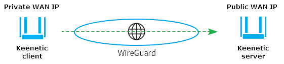
There is a Keenetic router with a public IP address for accessing the Internet. This router will act as a VPN server, and its public address will be used to connect another Keenetic (as a VPN client) with an IP address from the private range on the WAN interface.
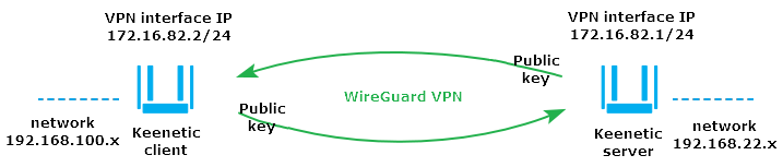
It is necessary to provide hosts of each router with access to the remote local network through a VPN tunnel. Such a connection scheme is also called a "Site-To-Site VPN" (for example, an inter-office connection to extend the network infrastructure).
Important
We recommend you configure WireGuard VPN from a single device (for example, a computer or a smartphone) because when creating a connection, you will need to exchange public keys on both sides of the VPN tunnel. So, you need to provide simultaneous access to the server and the client settings.
In the example, the server and the client are Keenetic routers, so open two web interfaces in your browser in different tabs simultaneously.
Proceed as follows on both devices:
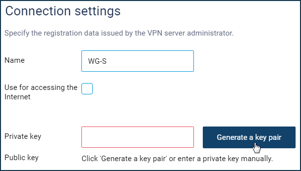
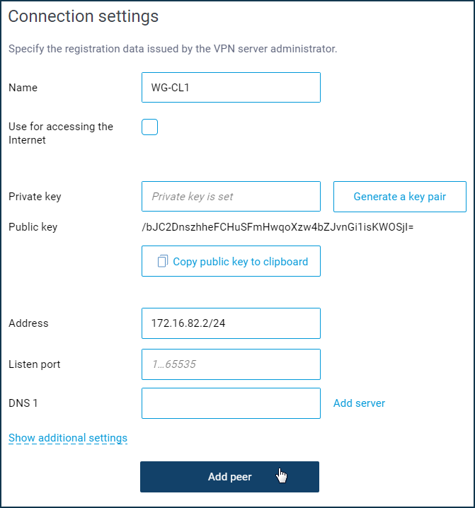
Go to the 'Other connections' page, and in the 'WireGuard' section, click 'Add connection'. You will see the settings page, where you can specify the name of the tunnel. In our example, the names are "
WG-S" for the server and "WG-CL1" for the client.
Click the 'Generate a key pair' button to generate a Private and a Public key. Further on, we will only need Public keys on both sides of the VPN tunnel. You will need to specify the key to the VPN server in the VPN client settings and vice versa.
Important
Do not close the browser tabs of WireGuard connections for the server and the client. You will need to switch between them during the configuration process.
Now let's have a look at the settings of each router in detail.
Setting the WireGuard VPN server
Enter the internal IP address of the tunnel in IP/bitmask format (in our example, 172.16.82.1/24) in the WireGuard connection settings in the 'Address' field. You can use any subnet in the private range that is not used on the server and the client sides.
In the 'Listening port' field, enter the port number that will be used when configuring the VPN client (in our example, it is port 16632). This port the client will use when setting up the tunnel. The router will automatically open this port on all interfaces to allow incoming connections to pass. There is no need to add any permissive firewall rules.
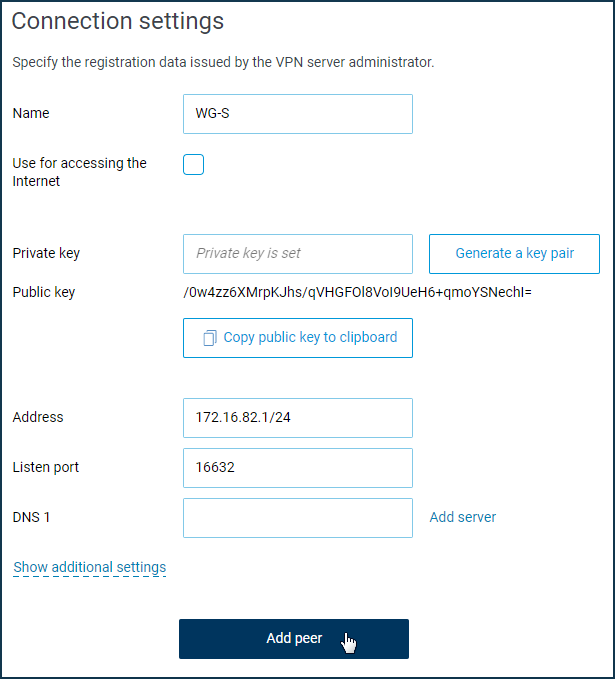
Click the 'Add peer' button to create client connection settings.
Switch your browser to the VPN client web interface tab temporarily and click 'Copy public key to clipboard' in the WireGuard connection settings ('WG-CL1').
Go back to the VPN server settings tab. Enter the peer's name (in our example, it's 'WG-CL1') and in the 'Public key' field, paste the VPN client's public key from the clipboard.
In the 'Allowed IPs' fields, you need to specify the addresses from which the remote side can send the traffic and to which the remote side can receive the traffic. Typically, these are the internal address of the remote end of the tunnel and the remote network (VPN client's local network).
Important
Address areas of allowed subnets in peers within the same interface should not overlap.
In our example, the address of the remote tunnel end is 172.16.82.2/32. On the VPN client side, the traffic in the tunnel will go with the source address 172.16.82.2, so we specify the host address (with /32 mask) here. And 192.168.100.0/24 is defined as the remote network (we must provide tunnel access to this network).
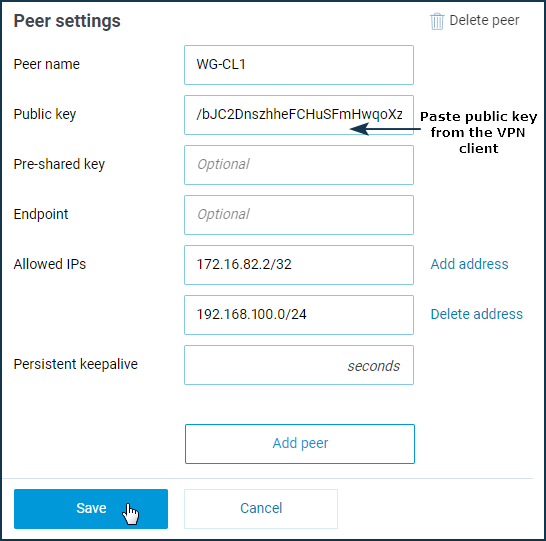
Click the 'Save' button.
The WireGuard connection configuration on the VPN server side is complete, but you also need to configure firewall rules and routing on the Keenetic. You need to allow incoming traffic and specify a static route to the remote network for the created WireGuard interface.
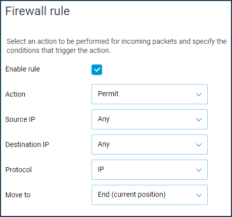
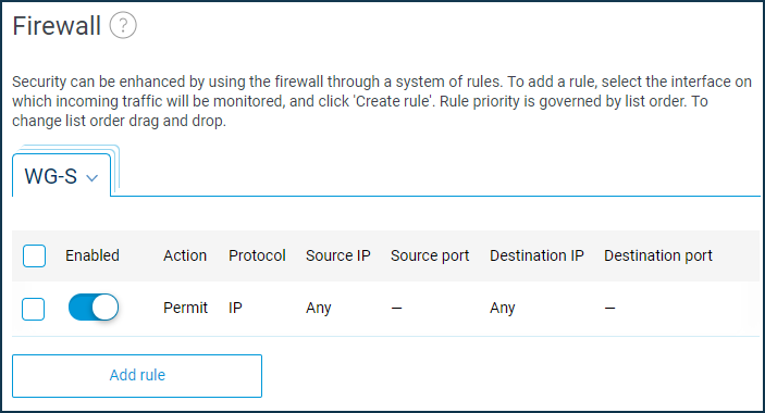
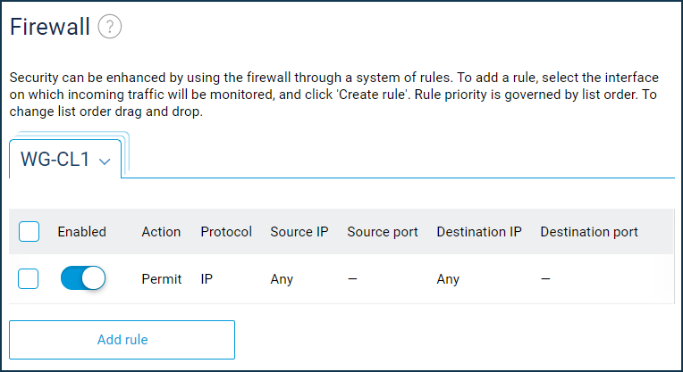
Open the 'Firewall' page. Add and enable an allow rule for the IP protocol for the WireGuard interface (in our example, this is 'WG-S'). It is necessary because, by default, the tunnel interfaces are set to a public security level, and incoming traffic is not allowed. You must make the relevant settings on both Keenetic routers so that requests from remote networks can pass through the tunnel.
You need to add a static route to send traffic to a remote network through a tunnel.
Go to the 'Routing' page, tap on 'Add route' and specify the following static route options:
In the 'Route type' field, choose the 'Route to network' option; in the 'Destination network address' field, specify the remote subnet (in our example, it is
192.168.100.0). And in the 'Interface' field, choose the name of the previously created WireGuard interface (in our case, it is 'WG-S'), enable the 'Add automatically' option.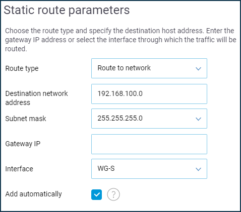
Now the VPN server configuration is complete, and you can move on to the VPN client settings. But first, open the 'Other connections' page, click on the record of the created WireGuard connection (in our example, it is 'WG-S'), and then click 'Copy public key to clipboard'. We will need this key to configure everything on the VPN client side.
Important
Often on a router, which acts as a VPN server, the administrator additionally configures the firewall to deny all incoming connections on the WAN interface and only allow connections from specific IP addresses. If you have such settings, add a rule to the firewall on the WAN interface for incoming connections to the WireGuard server. In the allow rule, you must specify the listening port number of the WireGuard server for the UDP protocol (in our example, it is port 16632). If this is not done, the VPN tunnel will not be established.
Setting the WireGuard VPN client
Enter the internal IP address of the tunnel from the same subnet as the VPN server in the WireGuard connection settings in the 'Address' field. Enter the IP address in IP/bitmask format (in our example, 172.16.82.2/24, since the address at the remote end of the tunnel is 172.16.82.1/24).
Click the 'Add peer' button to create server connection settings.
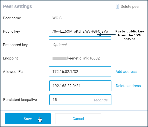
Specify the peer's name (in our example, it is 'WG-S') and in the 'Public key' field, paste the VPN server public key from the clipboard.
In the 'Endpoint' field, in IP:port or name:port format, enter the public IP address or the domain name of the router that performs the VPN server function, respectively, and via a colon the peer port (the listening port that was specified when configuring the tunnel on the server). In our example it is ****.keenetic.link:16632
Important
When using the KeenDNS service, make sure that it operates in the direct access mode. You will not be able to connect to a VPN server from the Internet when using cloud access mode.
In the 'Allowed IPs' fields, you need to specify the addresses from which the remote side can send the traffic and to which the remote side can receive the traffic. These are the internal address of the remote end of the tunnel and the remote network (VPN server's local network).
In our example, the address of the remote end of the tunnel is 172.16.82.1/32 (the traffic from the VPN client in the tunnel will go with the source address 172.16.82.1, and so we specify here the host address), and the remote network is 192.168.22.0/24 (you have to provide access to this network through the tunnel).
In the 'Persistent keepalive' field, choose the interval of attempts to check for peer activity (this is an internal check for the availability of the remote side of the connection). In our example, it is set to 15 seconds.
Click the 'Save' button.
Now we will configure the network screen and routing on the Keenetic. You need to allow incoming traffic and specify a static route to the remote network for the created WireGuard interface.
Open the 'Firewall' page. Add and enable an allow rule for the IP protocol for the WireGuard interface (in our example, this is 'WG-CL1').
To send traffic to a remote network through a tunnel, you need to add a static route.
Go to the 'Routing' page, tap on 'Add route' and specify the following static route options:
In the 'Route type' field, choose the 'Route to network' option; in the 'Destination network address' field, specify the remote subnet (in our example, it is
192.168.22.0). And in the 'Interface' field, choose the name of the previously created WireGuard interface (in our case, it is 'WG-CL1'), enable the 'Add automatically' option.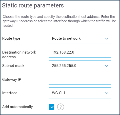
Now the configuration of the VPN server and the VPN client is complete.
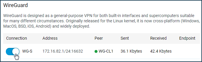
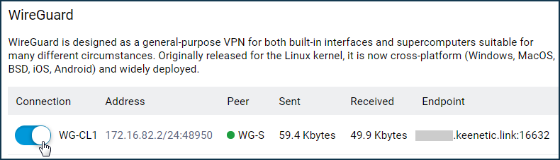
Enable the WireGuard connections created on both routers. If everything is set up correctly, you will see a green status indicator in the 'Peer' column.
VPN server:
VPN client:
The configuration is complete.
To test the VPN tunnel function from hosts or directly from the router (from the 'Diagnostics' menu in the web interface), ping the remote router or the devices outside the tunnel.
For example, from the host on the local network of the VPN client (from the network 192.168.100.x), we execute a ping command of the IP address of the VPN server (in our case, it is 172.16.82.1) and then a ping command of the local IP address of the Keenetic in the remote network behind the tunnel (in our example it is 192.168.22.1).
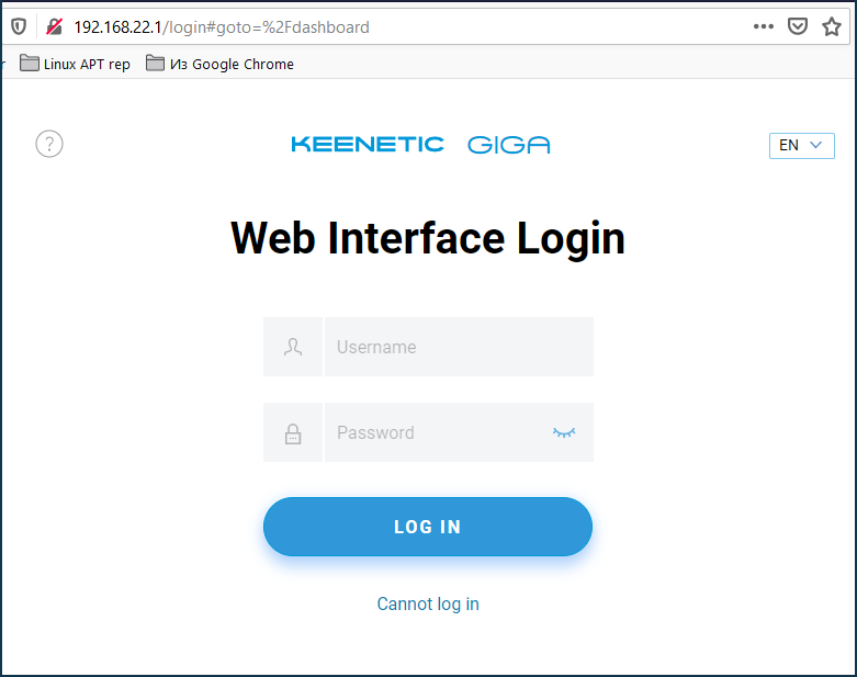
Check the server web interface (in our case, it is Keenetic with IP address 192.168.22.1).
Note
The configuration shown in this article will install a Wireguard VPN to allow access to the remote subnet behind the VPN tunnel. The local ISP will provide Internet access for the clients.
But in some cases, clients connected to the Keenetic router via WireGuard need to get Internet access through this VPN tunnel. So, you need to configure the connection so that all traffic is routed from the VPN client to the WireGuard tunnel, both to access the remote network and the Internet.
To do this, you will need to make additional settings on the client and server according to the instruction 'Internet access via WireGuard VPN'. Please note that in this case, the load on the VPN channel itself and on the Internet channel to which Keenetic (acting as a VPN server) is connected will increase.
If after configuring the VPN tunnel SMB access inside the tunnel does not work for Windows clients, it is usually caused by the Windows Defender or other firewall being enabled on the hosts. In this case, disable the firewall in Windows and check the operation.
Either fine-tune the firewall or Windows Defender. Create allow rules in Windows Defender for TCP/UDP ports:
UDP/137,UDP/138,TCP/139,TCP/445.In Kaspersky Internet Security, you need to allow local network access for the same
UDP/137,UDP/138,TCP/139,TCP/445ports and check the network access level for the network adapter.