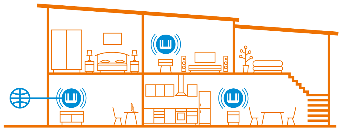
When you need to extend your Wi-Fi coverage in a large apartment, country house or small office, you can add more devices as Wi-Fi extenders to an existing Keenetic router. Connect them over Ethernet for maximum performance or over Mesh Wi-Fi without cabling. Keenetic devices included in the Wi-Fi System form a network with seamless 802.11k/r/v roaming and centralised management from the Wi-Fi System Controller (Keenetic Main Router).
For more information, see the What is the Wi-Fi System? article.
Note
The word 'Extender' refers to a Keenetic device in the universal operating mode: 'Amplifier + Access Point', which is being added to a Wi-Fi system.
Depending on the connection method (cable or Wi-Fi), the device automatically determines the desired operating mode. If the extender is connected to the existing network via Ethernet cable — the Access Point Mode is used; if the extender is connected via Wi-Fi — the Repeater Mode is used.
A Keenetic device can be used both as a router and as an extender. In some models, the operating mode is selected by a simple switch on the case, in other models via its web interface.

Mesh Wi-Fi (wireless extender connection) support has been added to all 2.4 / 5 GHz dual-band models (Carrier, Speedster, Skipper, Hero, Titan) in KeeneticOS 3.1.
Buddy models can only act as extenders.
A hidden access point (a wireless backhaul, SSID 'afb6450c906294c87fd6619c8f' or similar) has been added to all dual-band devices acquired in the Wi-Fi System, intended for communication of Wi-Fi nodes with each other.
Starting with KeeneticOS 3.3.1, the 2.4 GHz wireless backhaul connection is also possible.
Important
Mesh Wi-Fi technology works on Keenetics in the Repeater/Extender Mode.
Wireless connections between dual-band Extenders are only established in the 5 GHz band. This is due to the current capabilities of the Wi-Fi drivers. This is a current limitation of the Mesh Wi-Fi System design at the moment.
It is possible to connect an extender simultaneously over an Ethernet cable and a Wi-Fi network. In this case, the cable connection will take priority. If the cable is disconnected or the link to the controller is lost, the extender will establish a Wi-Fi connection (this switching takes about one minute). For switching to take place, the controller must have the wireless backhaul connection enabled.
Connection options of a Keenetic Mesh Wi-Fi Extender are shown in detail in the 'Connecting extenders to Mesh Wi-Fi System' instruction.
Useful additional information can be found in the articles:
Technical description
All nodes operating in Repeater/Extender Mode and acquired by the Wi-Fi Controller automatically configure the WifiMaster1/WifiStation0 interface to connect to a hidden SSID. This backhaul link uses the 4-address format of Wi-Fi headers, similar to WDS, containing Receiver's Address [RA], Transmitter's Address [TA], Source Address [SA] and Destination Address [DA], i.e., addresses of intermediate wireless nodes and LAN endpoints.

Home, Guest and other segments are multiplexed in wireless connections just like they are in wired connections — using VLAN 802.1q.
In each segment, the STP protocol is enabled to provide optimal link selection between extenders. Preference is given to wire connections. When an extender is connected via wire, a wireless connection is still established. Still, data transmission over the STA interface is blocked at the bridge level as long as the cable is connected.

When switched on, the extender selects the optimal access point based on its signal strength and the metric (distance to the controller) transmitted in the 'Probe response' packet. The metric is calculated from the root_path_cost STP value. In this way, the wireless extender can detect if the access point is connected to the controller and how far it is. The controller itself transmits a metric equal to one.
Tip
If an extender is connected through an intermediate switch, the switch must transmit the L2 level traffic fully transparently. The Wi-Fi system uses the STP protocol, and if the switch supports MSTP/RSTP/STP, these settings must be disabled on the ports used by the Wi-Fi system.
show mws member command in CLI shows the connection information for each extender:
parent identifier;connection interface;controller distance.
For example:
[
  {
    "cid": "9942687c-3e81-11e7-8489-0da3593493fa",
    "model": "Titan (KN-1810)",
    "mac": "50:ff:20:00:00:3a",
    ...
    "backhaul": {
      "uplink": "WifiMaster1/WifiStation0",
      "bridge": "8000.50:ff:20:00:01:0e",
      "cost": 50
  }
 },
 {
    "cid": "e5da6c72-e60d-11e8-8000-e975d199df10",
    "model": "Titan (KN-1810)",
    "mac": "50:ff:20:00:01:11",
    ...
    "backhaul": {
      "uplink": "WifiMaster1/WifiStation0",
      "bridge": "e000.50:ff:20:00:00:3a",
      "cost": 100
  },
 ...
The 8000 prefix means that the parent device is the controller, and e000 implies that the parent device is the extender.
When calculating the root_path_cost metric depending on the connection type to a parent device, the following constants are used:
4— port SFP5— GigabitEthernet port19— FastEthernet port50— 5 GHz Wi-Fi124— 2.4 GHz Wi-Fi
Actual speed, duplex, and link quality are not considered. Wi-Fi signal strength is only used when selecting the best point for a hidden SSID connection.
In the example above, two extenders are connected one after another by 5 GHz Wi-Fi, so the cost of the last one is 50+50=100.
Notice
Starting with KeeneticOS 4.1, the command mws stp priority has been added to allow you to prioritise a controller. It must necessarily become the root node in STP.
Command example:
mws stp priority 16384
system configuration save